vlan [id] and name, assign access ports with switchport mode access and switchport access vlan [id], and configure trunk ports with switchport mode trunk and switchport trunk allowed vlan [list]. Verify with show vlan brief and show interfaces trunk.VLAN configuration Cisco switch step by step is the foundational network segmentation skill for any engineer building or managing a business network. Whether you are separating staff traffic from guest Wi-Fi, isolating a finance VLAN from the general LAN, building a dedicated VLAN for IP phones, or meeting PCI-DSS segmentation requirements — VLANs on Cisco switches are the standard implementation method. Cisco’s VLAN configuration guide for Catalyst switches covers the full feature set, but this guide focuses on the practical deployment path.
I have performed VLAN configuration on Cisco Catalyst 2960 and 3750 switches across environments ranging from five-VLAN small offices to 40-VLAN warehouse networks with inter-site trunks. The configuration steps are consistent across IOS versions. This guide takes you from zero to a fully segmented, routed VLAN network with verified connectivity.
By the end you will be able to complete VLAN configuration on a Cisco switch step by step, configure access and trunk ports, set up inter-VLAN routing using router-on-a-stick and Layer 3 SVI interfaces, and fix the four most common reasons a VLAN stops passing traffic.
Table of Contents
- Why VLANs Matter for Network Segmentation
- Understanding VLAN Architecture and Key Concepts
- Lab Prerequisites and Topology
- VLAN Configuration Cisco Switch Step by Step
- Inter-VLAN Routing: Router-on-a-Stick
- Inter-VLAN Routing: Layer 3 Switching with SVIs
- Verification Commands
- Access Port vs Trunk Port: Key Differences
- Real-World VLAN Deployment Scenario
- Troubleshooting: VLAN Not Passing Traffic
- VLAN Best Practices
- FAQ: People Also Ask
- Conclusion
Why VLANs Matter for Network Segmentation
Without VLANs, every device connected to a Cisco switch shares the same broadcast domain. A single broadcast storm — from a misconfigured device, a spanning tree loop, or a worm spreading ARP floods — reaches every port on every switch in the building. VLAN configuration on Cisco switches solves this by creating isolated broadcast domains at Layer 2, with inter-VLAN traffic controlled at Layer 3 where routing policies and firewall rules apply.
In a typical SMB deployment, step by step VLAN configuration on Cisco switches delivers three concrete outcomes: security through isolation (finance traffic cannot reach the staff VLAN without passing through a firewall), performance (broadcast traffic from 200 staff devices does not saturate the 20-device management VLAN), and compliance (PCI-DSS requires cardholder data to be segmented — see PCI DSS standard documentation for segmentation requirements). The NIST SP 800-125B security guide also recommends network segmentation via VLANs as a baseline control for enterprise environments.
Understanding VLAN Architecture and Key Concepts
Key Concepts
- VLAN ID: A 12-bit identifier from 1 to 4094. VLANs 1 to 1005 are stored in the VLAN database (flash:vlan.dat). Extended range VLANs 1006 to 4094 are stored only in running-config. VLAN 1 is the default — never use it for user traffic.
- Access Port: A switch port assigned to exactly one VLAN. The connected end device has no knowledge of VLANs. Used for PCs, printers, IP phones, and wireless APs.
- Trunk Port: A switch port that carries multiple VLANs using 802.1Q tags. Used between Cisco switches, between a switch and a router (router-on-a-stick), or between a switch and a hypervisor.
- 802.1Q: The IEEE standard for VLAN tagging. Adds a 4-byte tag to the Ethernet frame containing VLAN ID, CoS priority bits, and drop eligibility indicator.
- Native VLAN: The VLAN whose traffic crosses a trunk port untagged. Must match on both ends — a mismatch generates a CDP warning and causes traffic problems. Always change native VLAN from the default VLAN 1.
- SVI (Switch Virtual Interface): A Layer 3 interface on a multilayer Cisco switch representing a VLAN subnet. Enables inter-VLAN routing without a separate router.
- VTP (VLAN Trunking Protocol): Cisco proprietary protocol that propagates VLAN database changes. Use transparent mode in most environments to prevent accidental VLAN database overwrites.
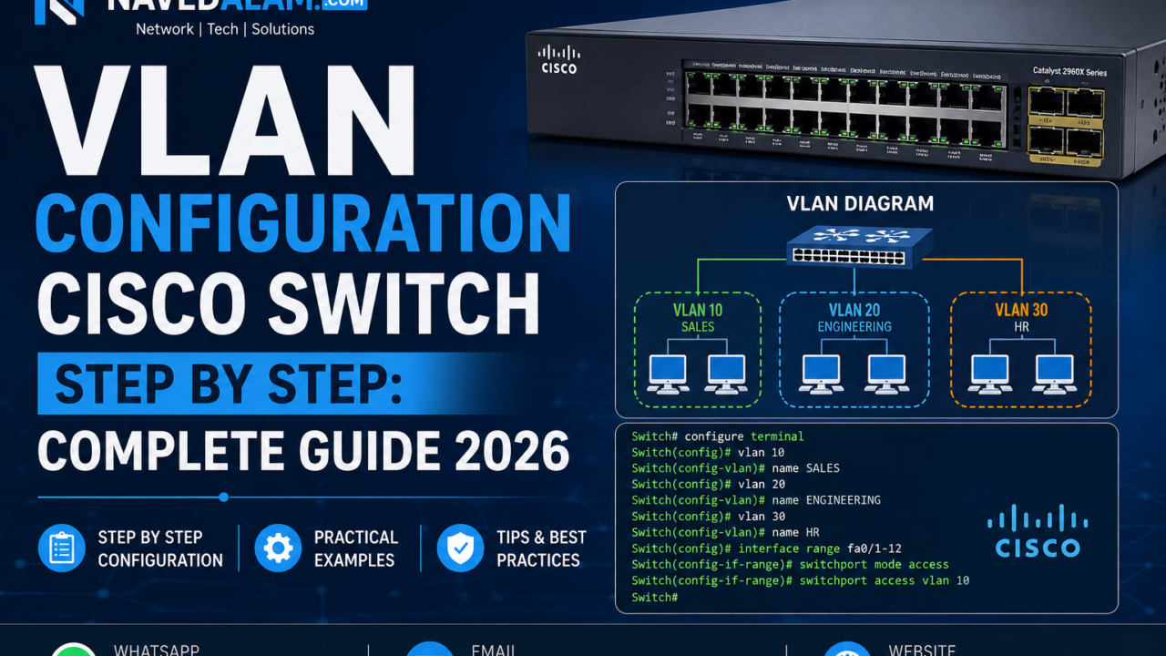
Lab Topology
                   [Router R1]
                        |
                   Gi0/0 (trunk)
                        |
           [SW1 - Cisco Catalyst 2960 / 3750]
          /              |
       Fa0/1-5         Fa0/6-10         Fa0/11-15
       VLAN 10         VLAN 20          VLAN 30
     (Staff)         (Finance)        (Management)
   192.168.10.0/24  192.168.20.0/24  192.168.30.0/24
Lab Prerequisites
- Cisco Catalyst switch — 2960, 3560, 3750, or equivalent in GNS3 / EVE-NG / Cisco Modeling Labs
- Cisco IOS 12.2(55)SE or later (all IOS-XE versions supported)
- Console or SSH access to the switch
- For inter-VLAN routing: a Cisco IOS router (15.x) or a Layer 3 capable switch
- Basic IOS CLI familiarity — enable mode, configure terminal, interface commands
VLAN Configuration Cisco Switch Step by Step
Follow these three phases in order. Creating VLANs before assigning ports prevents IOS from generating warnings about non-existent VLANs and ensures traffic is classified correctly from the moment a device connects. This is the correct sequence for VLAN configuration on any Cisco switch running IOS.
Phase 1: Create VLANs in the Database
The first step in VLAN configuration on a Cisco switch is always creating the VLAN in the database. Include a meaningful name — it appears in show vlan brief output and in switch logs, making operations significantly faster.
SW1# configure terminal

! Create VLAN 10 - Staff network
SW1(config)# vlan 10
SW1(config-vlan)# name STAFF
SW1(config-vlan)# exit

! Create VLAN 20 - Finance network
SW1(config)# vlan 20
SW1(config-vlan)# name FINANCE
SW1(config-vlan)# exit

! Create VLAN 30 - Management network
SW1(config)# vlan 30
SW1(config-vlan)# name MANAGEMENT
SW1(config-vlan)# exit

! Create VLAN 999 - dedicated native VLAN (never VLAN 1)
SW1(config)# vlan 999
SW1(config-vlan)# name NATIVE-UNUSED
SW1(config-vlan)# exit

SW1(config)# end
Verify all VLANs appear as active:
SW1# show vlan brief

VLAN Name                             Status    Ports
---- -------------------------------- --------- ----------------------------
1    default                          active    Fa0/16, Fa0/17 ...
10   STAFF                            active
20   FINANCE                          active
30   MANAGEMENT                       active
999 NATIVE-UNUSED activeshow vtp status. If the switch is in VTP Client mode, it cannot create VLANs locally. Run vtp mode transparent first, then recreate the VLANs.Phase 2: Configure Access Ports
Access ports are the second step in VLAN configuration on a Cisco switch. Always explicitly set switchport mode access — never rely on DTP auto-negotiation in production. Add spanning-tree portfast on every access port to eliminate the 30-second STP delay when devices connect.
! Assign Fa0/1-5 to VLAN 10 (Staff)
SW1(config)# interface range FastEthernet 0/1 - 5
SW1(config-if-range)# switchport mode access
SW1(config-if-range)# switchport access vlan 10
SW1(config-if-range)# spanning-tree portfast
SW1(config-if-range)# no shutdown
SW1(config-if-range)# exit

! Assign Fa0/6-10 to VLAN 20 (Finance)
SW1(config)# interface range FastEthernet 0/6 - 10
SW1(config-if-range)# switchport mode access
SW1(config-if-range)# switchport access vlan 20
SW1(config-if-range)# spanning-tree portfast
SW1(config-if-range)# no shutdown
SW1(config-if-range)# exit

! Assign Fa0/11-15 to VLAN 30 (Management)
SW1(config)# interface range FastEthernet 0/11 - 15
SW1(config-if-range)# switchport mode access
SW1(config-if-range)# switchport access vlan 30
SW1(config-if-range)# spanning-tree portfast
SW1(config-if-range)# no shutdown
SW1(config-if-range)# exit
Phase 3: Configure Trunk Port
The trunk port is the third step in VLAN configuration on a Cisco switch — it carries all VLANs between switches and to the router. Always specify the allowed VLAN list explicitly. Set native VLAN to 999, not VLAN 1. On Layer 3 switches (3750/3560), set the encapsulation type before setting the mode.
! On a Layer 3 switch (3750/3560) - encapsulation required first
SW1(config)# interface GigabitEthernet 0/1
SW1(config-if)# switchport trunk encapsulation dot1q
SW1(config-if)# switchport mode trunk
SW1(config-if)# switchport trunk allowed vlan 10,20,30
SW1(config-if)# switchport trunk native vlan 999
SW1(config-if)# no shutdown
SW1(config-if)# exit

! On a Layer 2 switch (2960) - no encapsulation command
SW1(config)# interface GigabitEthernet 0/1
SW1(config-if)# switchport mode trunk
SW1(config-if)# switchport trunk allowed vlan 10,20,30
SW1(config-if)# switchport trunk native vlan 999
SW1(config-if)# no shutdown
SW1# show interfaces trunk
Port Mode Encapsulation Status Native vlan
Gi0/1 on 802.1q trunking 999
Port Vlans allowed on trunk
Gi0/1 10,20,30
Port Vlans allowed and active in management domain
Gi0/1 10,20,30Inter-VLAN Routing: Router-on-a-Stick
Router-on-a-stick completes the VLAN configuration on a Cisco switch deployment by adding Layer 3 routing. A single trunk link connects the switch to a router, which routes between VLAN subnets using logical sub-interfaces — one per VLAN. Each sub-interface acts as the default gateway for that VLAN.
! On R1 - single physical interface, multiple sub-interfaces
R1(config)# interface GigabitEthernet 0/0
R1(config-if)# no ip address
R1(config-if)# no shutdown

! Sub-interface for VLAN 10
R1(config)# interface GigabitEthernet 0/0.10
R1(config-subif)# encapsulation dot1Q 10
R1(config-subif)# ip address 192.168.10.1 255.255.255.0
R1(config-subif)# exit

! Sub-interface for VLAN 20
R1(config)# interface GigabitEthernet 0/0.20
R1(config-subif)# encapsulation dot1Q 20
R1(config-subif)# ip address 192.168.20.1 255.255.255.0
R1(config-subif)# exit

! Sub-interface for VLAN 30
R1(config)# interface GigabitEthernet 0/0.30
R1(config-subif)# encapsulation dot1Q 30
R1(config-subif)# ip address 192.168.30.1 255.255.255.0
R1(config-subif)# exit
! Test inter-VLAN routing - from VLAN 10 PC ping VLAN 20 PC
C:> ping 192.168.20.50
Reply from 192.168.20.50: bytes=32 time=1ms TTL=127Inter-VLAN Routing: Layer 3 Switching with SVIs
On a Layer 3 Cisco switch (Catalyst 3560, 3750, 3850, 9300), you route between VLANs internally in hardware — no separate router needed. SVI (Switch Virtual Interface) routing is the preferred method for any deployment with more than three VLANs or more than 50 devices per VLAN, as it operates at line rate. This is the most scalable way to complete inter-VLAN routing after VLAN configuration on Cisco switches in medium and large environments.
! Enable IP routing on the Layer 3 Cisco switch
SW1(config)# ip routing

! Create SVI for VLAN 10
SW1(config)# interface vlan 10
SW1(config-if)# ip address 192.168.10.1 255.255.255.0
SW1(config-if)# no shutdown
SW1(config-if)# exit

! Create SVI for VLAN 20
SW1(config)# interface vlan 20
SW1(config-if)# ip address 192.168.20.1 255.255.255.0
SW1(config-if)# no shutdown
SW1(config-if)# exit

! Create SVI for VLAN 30
SW1(config)# interface vlan 30
SW1(config-if)# ip address 192.168.30.1 255.255.255.0
SW1(config-if)# no shutdown
SW1(config-if)# exit
! Verify all SVIs are up/up
SW1# show ip interface brief | include Vlan
Vlan10 192.168.10.1 YES manual up up
Vlan20 192.168.20.1 YES manual up up
Vlan30 192.168.30.1 YES manual up upComplete Verification Commands
! 1. Verify VLANs exist and are active
SW1# show vlan brief

! 2. Verify trunk is up and carrying all required VLANs
SW1# show interfaces trunk

! 3. Verify access port VLAN assignment
SW1# show interfaces FastEthernet 0/1 switchport
Administrative Mode: static access
Access Mode VLAN: 10 (STAFF)

! 4. Verify inter-VLAN routing table (Layer 3 switch)
SW1# show ip route
C    192.168.10.0/24 is directly connected, Vlan10
C    192.168.20.0/24 is directly connected, Vlan20
C    192.168.30.0/24 is directly connected, Vlan30

! 5. Ping between VLANs to confirm routing
SW1# ping 192.168.20.1 source vlan 10
!!!!!
Success rate is 100 percent
Access Port vs Trunk Port: Key Differences
| Feature | Access Port | Trunk Port |
|---|---|---|
| VLANs carried | One VLAN only | Multiple VLANs (802.1Q tagged) |
| 802.1Q Tagging | No — device unaware of VLAN | Yes — all frames tagged except native VLAN |
| Connected to | PCs, printers, IP phones, APs | Switches, routers, hypervisors |
| Key commands | switchport mode accessswitchport access vlan [id] |
switchport mode trunkswitchport trunk allowed vlan |
| PortFast | Always enable | Never enable |
| Native VLAN | Not applicable | Must match on both ends |
Real-World VLAN Deployment Scenario
A manufacturing company in Lahore with 180 employees needed to segment their flat network after a ransomware incident spread laterally across all devices. Every machine was on the same VLAN — once the malware entered through a compromised PC, it reached the accounts servers, the production line controllers, and the IP camera system with no barriers.
The VLAN configuration on Cisco 2960 and 3750 switches across four building floors involved four VLANs: Staff (VLAN 10), Production (VLAN 20), Management (VLAN 30), and Security Cameras (VLAN 40). Key decisions during the deployment:
- Native VLAN changed to 999 on all trunks. The previous VLAN 1 native configuration meant any untagged traffic — including CDP, STP, and VTP — was on VLAN 1 alongside users. Changing this was the highest-priority security fix in the entire VLAN configuration step by step plan.
- VTP set to transparent on all switches. The building had four access switches and one distribution switch. With transparent mode, each switch manages its own VLAN database locally. This eliminated the risk of a switch accidentally propagating a VLAN deletion to the entire network.
- BPDU Guard enabled on all access ports. One of the previous incidents had involved an unmanaged switch plugged into an access port, causing STP topology changes. A single
spanning-tree portfast bpduguard defaultcommand on each switch prevented this permanently. - Inter-VLAN routing controlled at the firewall, not the switch. Rather than using SVI routing for inter-VLAN traffic, all inter-VLAN routing was passed through a FortiGate firewall via a Layer 3 routed interface — allowing the security team to enforce ACLs between VLANs. Production (VLAN 20) has no access to Staff (VLAN 10) except specific allowed ports.
Results: The production network has been clean since deployment. The next ransomware attempt — identified three months later through firewall logs — was isolated to two workstations in VLAN 10 and never reached the production controllers or accounts servers.
Troubleshooting: VLAN Not Passing Traffic
These four issues account for over 90% of VLAN not passing traffic problems on Cisco switches. Work through them in order before escalating.
Issue 1: VLAN Not Active — VTP Client Mode
Symptoms: VLAN shows as “act/lshut” in show vlan brief or is missing entirely from the output.
Root cause: The switch is in VTP Client mode and cannot create VLANs locally — the VLAN must come from the VTP Server. In the absence of a VTP server, the VLAN simply does not exist on the switch.
SW1# show vtp status
VTP Mode: CLIENT

! Fix
SW1(config)# vtp mode transparent
SW1(config)# vlan 10
SW1(config-vlan)# name STAFF
Issue 2: VLAN Not in Trunk Allowed List
Symptoms: Devices in a VLAN cannot reach their gateway or other VLANs despite correct access port configuration on the Cisco switch.
Root cause: The VLAN was created after the trunk was configured and was never added to the allowed list.
SW1# show interfaces GigabitEthernet 0/1 trunk
Vlans allowed on trunk: 10,20
! VLAN 30 missing

! Add without removing existing VLANs
SW1(config-if)# switchport trunk allowed vlan add 30
Issue 3: Native VLAN Mismatch
Symptoms: CDP log: “Native VLAN mismatch discovered on GigabitEthernet0/1.” Untagged traffic on the native VLAN is unreliable.
Root cause: Native VLAN does not match on both ends of the trunk.
SW1# show interfaces Gi0/1 trunk | include Native
Native vlan: 999

SW2# show interfaces Gi0/1 trunk | include Native
Native vlan: 1   <- mismatch

! Fix on SW2
SW2(config-if)# switchport trunk native vlan 999
Issue 4: SVI Down Because No Active Port in VLAN
Symptoms: Inter-VLAN routing fails for one VLAN. show ip interface brief shows that VLAN SVI as “down/down”.
Root cause: A VLAN SVI comes up only when at least one access port in that VLAN is physically connected and up/up. No active ports = SVI stays down regardless of configuration.
SW1# show vlan id 20
VLAN 20   FINANCE   active   <- no ports listed

SW1(config)# interface FastEthernet 0/6
SW1(config-if)# switchport mode access
SW1(config-if)# switchport access vlan 20
SW1(config-if)# no shutdown

! SVI comes up automatically
SW1# show ip interface brief | include Vlan20
Vlan20   192.168.20.1   YES manual up   up
VLAN Best Practices for Cisco Switches
Design
- Never use VLAN 1 for any user or management traffic. VLAN 1 is the default and has been the target of VLAN hopping attacks. Cisco’s own VLAN security best practices guide recommends changing the native VLAN on all trunks and removing VLAN 1 from all trunk allowed lists.
- Use VTP transparent mode. VTP server/client propagation has caused production outages when a switch with a higher revision number overwrites the VLAN database. Transparent mode is safer and has no operational downside in environments with fewer than 15 switches.
- Explicitly list allowed VLANs on every trunk. Use
switchport trunk allowed vlan [list]— neverallowed vlan all. Explicit lists are self-documenting and prevent future VLANs from silently appearing on trunks where they should not be.
Security
- Enable port security on access ports to limit MAC address count and prevent MAC flooding attacks that target the VLAN configuration on Cisco switches.
SW1(config-if)# switchport port-security
SW1(config-if)# switchport port-security maximum 2
SW1(config-if)# switchport port-security violation restrict- Shut down and quarantine all unused ports. Assign them to a dead VLAN with no SVI, no routing, and no trunk membership.
SW1(config)# interface range FastEthernet 0/20 - 24
SW1(config-if-range)# switchport access vlan 999
SW1(config-if-range)# shutdown
Operations
- Enable PortFast and BPDU Guard globally. PortFast eliminates the 30-second STP delay on access ports. BPDU Guard shuts the port if a BPDU is received, blocking rogue switches.
SW1(config)# spanning-tree portfast bpduguard default- Document your VLAN table. A spreadsheet with VLAN ID, name, subnet, purpose, and trunk ports is the single most valuable document for any network running VLAN configuration on Cisco switches — it saves hours during incidents and onboarding.
FAQ: People Also Ask
How do I configure a VLAN on a Cisco switch?
VLAN configuration on a Cisco switch step by step requires three commands: vlan [id] to create the VLAN, switchport mode access and switchport access vlan [id] to assign access ports, and switchport mode trunk with switchport trunk allowed vlan [list] for trunk ports. Verify with show vlan brief. The full process takes under five minutes per VLAN on any Cisco IOS switch.
What is the difference between access port and trunk port on a Cisco switch?
An access port carries traffic for a single VLAN with no 802.1Q tagging — used for end devices. A trunk port carries multiple VLANs simultaneously with 802.1Q tags — used between Cisco switches, between a switch and a router for inter-VLAN routing, or between a switch and a hypervisor. Never connect an end device to a trunk port in a production VLAN configuration on a Cisco switch.
How does inter-VLAN routing work on a Cisco switch?
Devices in different VLANs are in different IP subnets and cannot communicate at Layer 2 — a Layer 3 device must route between them. Router-on-a-stick uses sub-interfaces on a router connected via trunk link. Layer 3 SVI routing uses virtual interfaces on a multilayer Cisco switch with ip routing enabled — routing inter-VLAN traffic in hardware at line rate without a separate router.
Why is my VLAN not passing traffic on a Cisco switch?
The four most common causes are: the VLAN is not in the trunk allowed list (fix with switchport trunk allowed vlan add [id]), the VLAN does not exist in the VLAN database on one of the switches, a native VLAN mismatch on the trunk is causing frame drops, or the SVI for that VLAN is down because no active access port is assigned to it. Start every diagnosis with show vlan brief and show interfaces trunk.
Related Articles
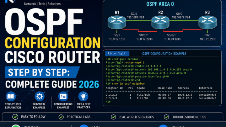
- OSPF Configuration Cisco Router Step by Step: Complete Guide 2026
- Cisco ASA Configuration Guide: Complete Firewall Setup 2026
- Network Troubleshooting Guide: Complete Fix 2026
- Remote Access VPN Configuration: Cisco IOS and ASA Guide 2026
Conclusion
VLAN configuration Cisco switch step by step comes down to four rules done correctly: always create VLANs before assigning ports, explicitly set every port as access or trunk (never rely on DTP), specify the allowed VLAN list on every trunk deliberately, and use a non-VLAN-1 native VLAN on every trunk. Get these right and your VLAN configuration will pass traffic reliably and stay stable across reboots, IOS upgrades, and topology changes.
- Never use VLAN 1 — create a dedicated native VLAN and assign all unused ports to a dead VLAN.
- Explicitly list trunk allowed VLANs — never use
allowed vlan allin any production VLAN configuration on a Cisco switch. - Use VTP transparent mode — prevents accidental database overwrites in environments without dedicated VTP management.
- Enable PortFast and BPDU Guard globally — eliminates STP delays on access ports and blocks rogue switch injection.
- Document your VLAN table — VLAN ID, name, subnet, and trunk membership saved in a spreadsheet is the most valuable operational document for any Cisco switch network.
After mastering VLAN configuration on Cisco switches step by step, the next topics are STP tuning with Rapid PVST+ and deliberate root bridge placement, followed by building a full three-tier campus design combining VLANs, OSPF, and redundant uplinks.
Need Expert Help with VLAN Design or Network Segmentation?
I provide professional network design and deployment services for SMBs and enterprises across Pakistan and internationally. Whether you need a complete VLAN architecture designed from scratch, a segmentation audit on an existing Cisco switch network, or emergency troubleshooting on a specific VLAN issue — I can help remotely or on-site.
- VLAN design and Cisco switch configuration
- Network segmentation architecture for compliance (PCI-DSS, ISO 27001)
- Cisco routing and switching deployment
- Firewall policy and inter-VLAN security design
- Azure and AWS cloud networking
Email: itexpert@navedalam.com
WhatsApp: +92 311 935 8005
Website: navedalam.com
Free 30-minute consultation — no obligation.
About the Author
Naveed Alam is a certified Network and Cloud Engineer specialising in Cisco switching, VLAN architecture, and enterprise segmentation design. He holds CCNA, AZ-900, and CompTIA A+ certifications and has designed and deployed VLAN configurations on Cisco switches for organisations ranging from 20-user SMBs to 1,000+ user enterprises across Pakistan and internationally.
Connect: LinkedIn · navedalam.com · itexpert@navedalam.com